Dave Wellings Spare Wheel Well
I managed to get half a day to myself, and took the luggage carrier and spare wheel off to see if I could smarten things up a bit.
There's not much scope under there.
The rear frame 'bonnet catches' have a wire which is supposed to run in a groove in the wood, but on mine is a bit slack.
I've held it up by slotting a plastic tube behind the centre rear brakelamp bracket.
All I could do was to add some thin neoprene to stop the tyre rubbing on the metal plate and cross timbers.
I also blew the metal plate over with some satin black, and added a bit more wax rust proofing.
I didn't take a 'before' picture, but here's the result.
The neoprene shows up as four triangles, and there's a thin horizontal strip where the inner part of the wheel rests, plus a piece on each of the horizontal timbers.
It's as tidy as I can make it for now.

Was it really March 09 when I did this.........
Time to add some detail I think. I've been busy tonight.....
First - on the left side cross-member there is the production spec in black marker pen.
So mine is R/H - (right hand drive I suppose) - V6 - with over-riders.

Then - tucked up behind the fuel filler tube is the chassis number - it's upside down (not the photo)........

Just right of centre of this photo is the main chassis earth - bolted to the chassis, offside.

Here are the offside connectors:

Nearside:

And tucked away under the rear valance over to the nearside........

More to come..........
This picture is looking down on the rear valance inside the spare wheel well.
You can just make out two slotted holes below, and to the right of the fasteners.
There are three of these fasteners, (allen headed setscrews with locknuts below) and the next photo shows this better.

With those three fasteners removed, it's now clear what happened.
The slotted holes were to allow adjustment, but the panel is very slightly too deep to line up.
So, I suspect that the compromise to make it fit was to offset the panel slightly to the right to avoid opening up the slotted hole into an over-large inverted T shape.

The effect is that the rear panel is offset slightly to the right, and my observations are that most early Roadsters seem to be the same.........
Here's the nearside gap......immediately below is the offside gap, and you can just tell the difference.


This has been niggling for a year.
The remaining fasteners on this panel are four cross-head self-tappers with penny washers which locate vertically upwards into the wood frame.
Two are outboard of the over-riders and two are inboard.
Tonight I had then all off, and using my pin chuck to mark up, then Dremel drill, I slotted the seven holes and relocated the rear panel centrally.
It was one hell of a fiddle, but now I can rest easy.
The best part of this exercise though..........is still to come............
Do you know worrit is yet???

How about now????

I've had this little project in mind for quite a while, but until now hadn't found a fix.
But now I have, and what a success this is.
The pictures tell the story.
This is self coloured 5mm acrylic (perspex) sheet.
I tried both red and black to see which looked best.
I'll let you decide.........
First the black.....

Then the red.......


I took a lot of care to get the measurements right and had these laser cut and the edges polished.
http://www.theplasticman.co.uk/
They are such a good fit that you could run with them on the road as dirt barriers were it not for the heat from the brakes (and lack of air flow!!!!!)
They hold in place with (you guessed it) two small pieces of neoprene at 180 degrees on the edge.
And here's the result. I'm so pleased with this........


And that's all for now..........
Time for a cuppa....
...........................................
Some Comments..........
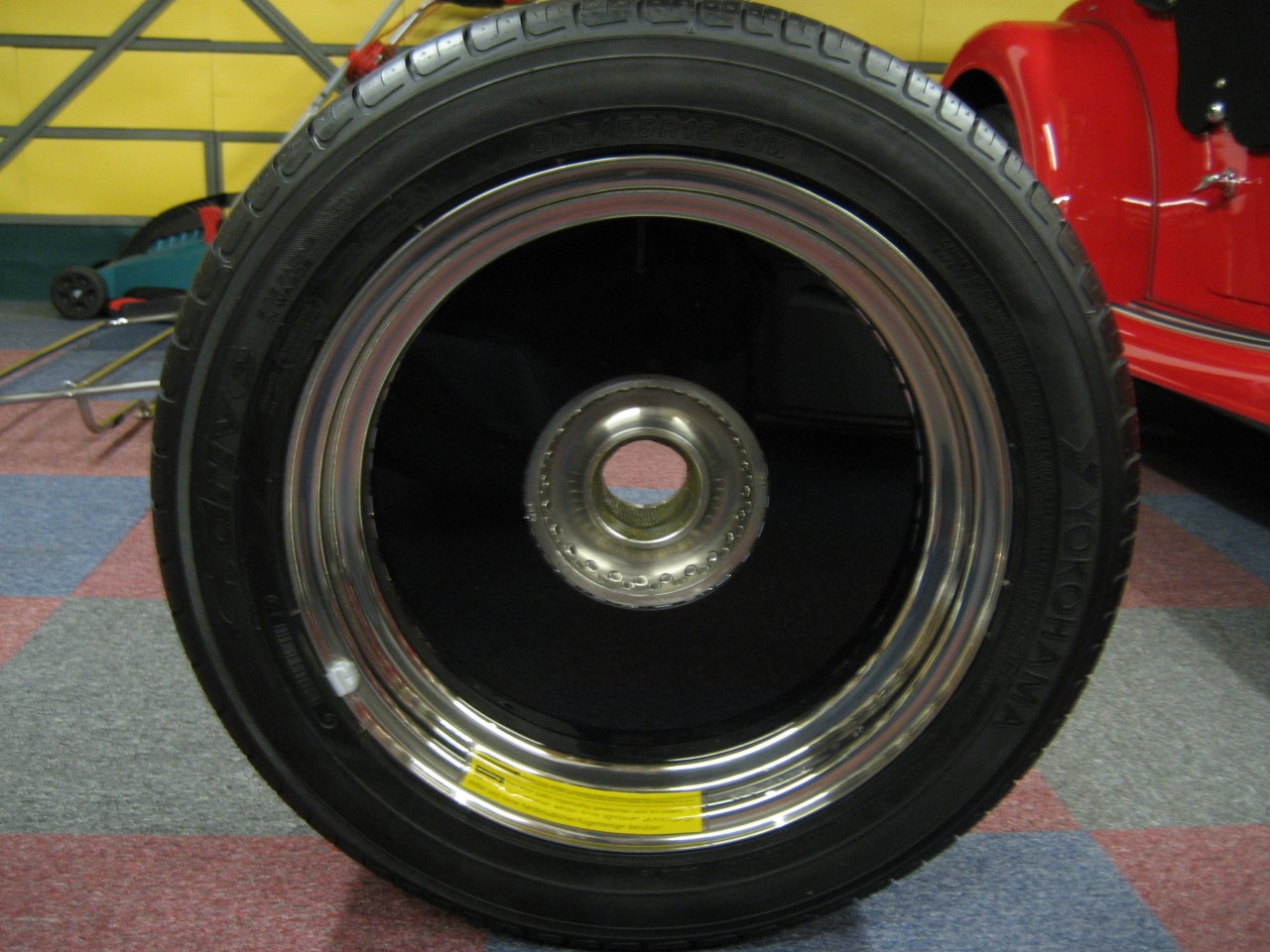
You need to measure (really accurately) across the inside of the centre hub (Roadster is 160mm) and put a straight edge across the inside from rim to rim (Roadster is 360mm).
Lay a straight edge across the inside of the 'centre hub'.
It must be exactly centred.
The plastic sits over the 'centre hub' against the spokes, so wherever the straight edge touches the rim, the measurement should be to just underneath it.
Look at the photos above on this thread showing the back of the wheel.
I would imagine that all recent centre hubs are the same size, although chrome wheels may be different, and the 160mm is such a tidy metric size that I'm guessing that at some stage in the past there would be an imperial measurement!!!!!!!!!
I can't remember the size of my wheels offhand (17"??), but I would be surprised if the +4 and 4/4 were exactly the same.
With a bulk order (to save on P&P), the unit cost would be 'around' £20.
Various colours are available, like Red / Yellow / Black / Clear.
I gambled that the red would match, and it does, but also got the black one as a fall back.
The black also looks really good, so I could vary it according to mood........
For metallics and non basic colours, then the plastic would need painting to match, or left black.
Incidentally, I'm also working on a Perspex wind-shield for behind the seats at Mrs. W's request, but like the spare wheel security device, it's proving to be a real challenge since I don't want to use bungee fasteners like the one which used to be sold in Miscellany, and I don't want to drill the car either.
So I'm using the head restraint stalks as locators, but as yet it won't stay vertical.
I'm having to do some special brackets..... but more of that later if I can make it work.
If successful it could be done for under £100.
.............................................

My Crimson insert thanks to your laser cutter.
Looks good. Many thanks, Dave.
Looks good. Many thanks, Dave.
....................................................
Followed on from Dave Ws solution to "tart up" my spare wheel.
Really pleased with outcome.
Total Cost £28.
Spare Wheel before.
Really pleased with outcome.
Total Cost £28.
Spare Wheel before.

Kit of Parts.
Silver 5mm perspex disc, Felt disc (to go against wheel hub, Mouse mat foam disc ( to go against wheel mounting bracket anti vibration,5mm "U" section edging strip.

Upside finished

Down side finished

Spare Wheel after

Regards. Ian
..........................................

Good morning Mr Wellings, I am an owner of a 2014 Morgan Roadster with just 4200 miles recorded very occasionally I experience power loss when accelerating from a low speed, the engine does not stop and I quickly gain speed. I would appreciate any suggestions with my problems please.
ReplyDeleteI look forward to hearing from you.
Regards,
Martin Weller member number 14664.